
 |
Country: Spain |  |
||
| Get funded free access to this facility via the ERIGrid 2.0 Lab Access Programme. |
||||
| Submit Testing/Consulting Request | ||||
Description: TECNALIA Research & Innovation is the first private Research, Development and Innovation (R&D&I) organization in Spain and one of the leading ones in Europe, with a staff of 1500 experts (including 192 Doctors), 22 headquarters and a turnover of 120 million Euro.
The mission of TECNALIA is to transform knowledge into GDP, improving people’s quality of life by generating business opportunities for companies. To accomplish this, TECNALIA is organised in 7 interconnected sectorial Divisions: Energy and Environment Division, Sustainable Construction Division, Industry and Transport Division, ICT – European Software Institute Division, Innovation Strategies Division, Health Division, and Technological Services Division.
TECNALIA’s offer includes different activities: technological services, testing and certification, R&D&I projects, transfer of industrial property, business promotion, business diversification, innovation management and foreign support.
The Smart Grids Area, included in the Energy and Environment Division, is focused on:
- Advanced power system architectures: microgrids for buildings and districts
- Demand side management and demand response
- Energy management and optimization in buildings
- Integration of Distributed Energy Resources in the network
- New power converters for grid connection
- Communication for Smart Grids and smart metering applications
- Electric mobility: infrastructure, grid integration and V2G applications
- Business models analysis and development
THOR Laboratory
Description: The core of THOR Laboratory is a 4-quadrant fully programmable voltage source in the power and voltage ranges of up to 1.25 MW and 3300 V respectively. Frequency variations of the output voltage from 0 to 75 Hz as well as generation of programmable sets of voltage harmonic components up to the 10th harmonic are possible. The flexible grid can be used as a grid emulator to test power converters. Possible equipment for tests are: Wind converters, energy storage converters, traction converters and grid power quality devices like STATCOMS, FACTS or active filters. A SCADA system controls the labs' parameters.
The following cases can be investigated at THOR Laboratory:
- Voltage and frequency variations
- Reactive power control behaviour
- Active power control behaviour
- Faults
- Harmonics
- Flicker
Furthermore, a new walk-in high-low temperature test chamber is included:
- Test space dimensions (WxHxD): 2640 x 2400 x 4160 mm
- Temperature range: -45ۃ to 85ۃ
- Humidity range: 10% to 95% RH
Centre for Development and Demonstration of DER Technologies (Microgrid)
Description: Coupled to the 30 kV radial network, the microgrid formed by different generation, storage devices, loads, with a manageable power of 200 kVA. The facility deals with the connection, integration and validation of technologies related to DER including EV, as well as with the operation and control strategies of the entire microgrid.
Technical specifications (PDF)
Description: 1120 Ah battery bank (24 V DC): single-phase coupling using one Xantrex SW 3024 inverter. – 1925 Ah battery bank (48 V DC): three-phase coupling using three Xantrex SW 3048 inverters.
Converters
Description: Different rectifier-based DC sources, AC/AC converters, power electronic devices for network quality improvement (DGFACTS), 4Q full converters, etc.
Diesel generator
Description: The diesel generator units consists of a diesel motor (John Deere ֠55 kW) and a three phase synchronous generator (400V, 50 Hz, 63 kVA). The controllable rectifier accepts a 380 Vac 3-phase voltage and provides a external-controllable (4-20 mA) output from 540 Vcc to 780 Vcc 100 A maximum.
Flywheel UPS Caterpillar Flywheel UPS
Description: Uninterruptible power supply system based on flywheel energy (instead of batteries). It reaches full charge at 7.700 rpm (less than 150 seconds recharge). From 4.000 rpm the UPS is in normal operation regulating output voltage and supplying reactive and harmonic currents required by the load. It also provides constant power protection against surges, sags and power interruptions during 15 seconds at full capacity (250 kVA)
Fuel cell
Description: PEM-type Ballard Fuel Cell, Nexa model, with 1.2 kW nominal power. As the FC supplies an unregulated voltage output, it comes together with a DC/DC converter and it does include algorithms for battery charge control. This device is normally used connected to the 1.5 kW DC load.
Microgrid switching and connection system
Description: ՠ3 three-phase buses with neutral (to accommodate single-phase devices). The buses can be connected between them ՠAny of the generation, storage or load systems can be connected to any of the buses (3×20 matrix of 4-poles contactors) ՠInterconnection to the distribution network ՠThe controller provides a local HMI (touch screen) and an OPC server as the interface to a remote SCADA (via Ethernet) ՠInterbus-S system control system ՠSecurity strategies have been implemented (exclusion,ũ
MAGNETEK EG-50 Microturbine
Description: The EG system is made up of two main parts, the turbine generator and the AC-AC converter. The turbine is supplied with liquid fuel (gas-oil) and rotates at up to 60.000 rpm. The generators output is a 380 Vac 400 Hz 3-phase voltage which represents the input of the subsequent stage of the AC-AC converter. The AC-AC converter generates a delta 480 Vac 60 Hz or star 380 Vac 50 Hz.
Pacific Power Source 3060-MS Network simulator
Description: Two parallel connected 3-phase simulators provide voltage 228/132 Vac up to 500Hz creating an AC voltage and frequency reference for testing purposes, one controllable DC voltage network generated through rectifier and inverter.
Photovoltaic installations
Description: The single-phase 0.6 kW pthotovoltaic installation is based on 13 UF42 modules (amorphous structure) and a SunnyBoy 700 Inverter. The other single-phase 1.6 kW pthotovoltaic installation is based on 16 Isofoton I-106CR modules (mono-crystalline structure) and a Xantrex SW 3024 Inverter. The three-phase 3.6 kW photovoltaic installation is based on 24 BP SX 150 S modules (multi-crystalline structure) and three SunnyBoy 1100 Inverters.
AVTRON K596 Reactive load bank
Description: 2 x 36 kVA
AVTRON K595 Resistive load bank
Description: 33.75 kW
AVTRON Millenium 150 Resistive load bank
Description: 150 kW
Transmission line simulator
Description: One configurable line simulator being possible to adjust the magnitude and angle of the circuit that is supposed to be connecting the generation and the consumption. The simulator has capability of different impedances selection.
Ultracapacitor bank
Description: 5 kW ultracapacitor-based UPS designed by EPRI PEAC Corporation. The 48V DC link of the UPS is connected to a bank of eight ultracapacitor modules. Each module is rated at 4500 F and is able to store 360 kJ of energy. This system is able to support the full load for about 6,5 minutes.
INCLIN NEO 6000 Wind turbine
Description: Wind turbine with a nominal power of 6 kW equipped with a three blades rotor (4 m), automatic brake system by tilt up and neodymium magnet alternator.
Description: 3 three-phase buses
Bonneville Power Administration + User contributio ATP-EMTP
Description: Power system analysis software (electromagnetic transients)
Dranetz-BMI Signature System (Infonod
Description: Power quality analyser. Integrated, web-based platform that allows users to remotelyءnd in real timeحonitor their power systems. A Signature System incorporates multiple measuring and monitoring units
Dranetz-BMI PX5
Description: Power quality analyser
LEM TOPAS 1000
Description: Power quality analyser
PSERC MATPOWER
Description: Power system analysis software (load flow and optimal power flow)
Siemens SINCAL
Description: Power system analysis software
Siemens PTI PSS/E
Description: Power system analysis software
The MathWorks MATLAB (PSB) – Simulink
Description: Power system analysis software
Characterization and accelerated test lab
Description: The lab includes techniques for : Substrate, cell and encapsulant chemical composition, microstructural morphology and optical properties characterisation. The instrumentation comprises SEM-EDS, AFM, XPS, FTIR, Raman and UV-Vis spectroscopy; Equipments for adhesion, hardness and scratch resistance of the encapsulation system; Equipments for gloss and colour change measurements of the modules; An equipment and test procedure specifically developed for wind particle abrasion testing. Equipments for accelerated lab tests include chambers for UV aging chamber, temperature and humidity cycling, and salt spray.
Technical specifications (PDF)
Electrical Equipment Laboratory
Description: Conformity Assessment and Certification Services of Electrical Equipment for T&D networks and industrial applications, to certify compliance with national and international standards, regulations and technical specifications from utilities and manufacturers. The 5000mҠarea lab is in operation since 1991 and covers a range of 300 MVA. It is run by 39 employees.
Technical specifications (PDF)
Power Laboratory
Description: Power Laboratory (shortcircuit, making and breaking, etc) 150 kA at LV (under 1000 V); 300 MVA at MV (up to 36 kV)
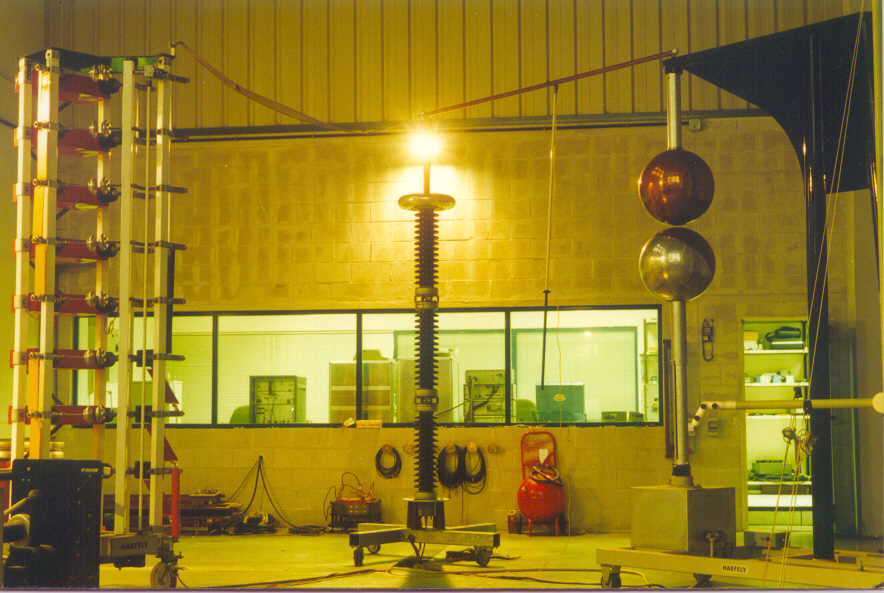
HV Laboratory
Description: HV Laboratory (dielectric, PD, Tan Delta, etc) 550 kV at power frequency 1.800 kV at lightning impulse
LV Laboratory
Description: LV Laboratory (PI, temperature-rise, climatics, etc)
Environmental Tests Laboratory
Description: Large climatic chamber 5,5x4x4 m
Power Electronics Laboratory
Frequency Resonant Unit
Description: Variable Frequency Resonant Unit: 260 kV, 80 A, 20-300 Hz
EMC Semianechoic Chamber
Description: The semi-anechoic chamber is the main facility for EMC tests in TECNALIA. It has the following inner dimensions: 8.4 x 4.9 x 5.4 m (height). Walls and ceiling are covered by a double absorbing system: ferrite tiles and polyurethane foam absorbers. The chamber is used for radiated emission measurements from 10 kHz to 12 GHz and for radiated immunity tests in the range of 80-3000 MHz. Equipments to be tested are placed in a 2m diameter rotatory platform, which is designed for supporting more than 500 kg. Usual distance between equipment under test and antenna is 3 m. TECNALIA is accredited by ENAC (the Spanish member of EA, ILAC and IAF) for the most employed European EMC standards and it is a Notified Body under the 2004/108/CE Directive (European EMC Directive).
Technical specifications (PDF)
Description: Electric field probe
Amplifier Research 500A100
Description: RF amplifier
Amplifier Research 100W1000M1
Description: RF amplifier
CHASE CBL 6111
Description: Bilog antenna (30-1000 MHz)
CHASE DIA1512
Description: Clicks analyser
EMC PARTNER MIGOS-OS1
Description: Damped oscillatory wave generator
EMCO 3104C
Description: Biconical antenna (20-200 MHz)
EMCO 3146
Description: Log-periodic antenna (100-1100 MHz)
EMCO 3142B
Description: Bilog antenna
EMCO 3115
Description: Horn antenna (1-18 GHz)
EMTEST ESD30+P18
Description: ESD generator
EMTEST EFT 503
Description: EFT generator
FCC F-61
Description: Current probe (1-1000 MHz)
FCC F-120-9
Description: Current probe (10 kHz-200 MHz)
Hewlett-Packard 11940A-11941A
Description: Magnetic near field probes (9 kHz-1 GHz)
Hewlett-Packard 8566B
Description: Spectrum analyser (100 Hz-22 GHz)
Hewlett-Packard 8591A
Description: Spectrum analyser (9 kHz-1,8 GHz)
Hewlett-Packard 54522A
Description: Digital Oscilloscope
Hewlett-Packard Infinium
Description: Digital Oscilloscope
LANGER RF1,2,3
Description: Magnetic near field probes (30 MHz-1 GHz)
MILMEGA AS0104
Description: RF amplifier
PMM EHP-50A, EP-330, EP-33M,
Description: Electric and magnetic field probes
PMM 1000
Description: Harmonic and flicker analyser
PMM L2-16
Description: Artificial mains network
PRODYN AD-20
Description: Electric near field probe (200 kHz-3 GHz)
Rohde & Schwarz HUF-Z2
Description: Biconical antenna (20-200 MHz)
Rohde & Schwarz HUF-Z3
Description: Log-periodic antenna (200-1000 MHz)
Rohde & Schwarz HFH2-Z2
Description: Loop antenna
Rohde & Schwarz HZ-14
Description: Electric and magnetic near field probes (9 kHz-1 GHz)
Rohde & Schwarz ESH3
Description: EMI receiver (9 kHz-30 MHz)
Rohde & Schwarz ESPV
Description: EMI receiver (20 MHz-1300 MHz)
Rohde & Schwarz ESCS30
Description: EMI receiver (9 kHz-2750 MHz)
Rohde & Schwarz ESH2-Z5
Description: Artificial mains network
Rohde & Schwarz ESH3-Z5
Description: Artificial mains network
Rohde & Schwarz SMHU
Description: RF signal generator
SCHAFFNER NSG-433
Description: ESD generator
SCHAFFNER NSG-1025
Description: EFT generator
SCHAFFNER NSG 651
Description: Surges generator
WALKER SCIENTIFIC ELF-50D
Description: Gaussimeter
INGRID - Smart Grids Testing and Research Infrastructure
Description: The key research and testing activities of this laboratory are: advanced power system architectures, microgrids for buildings and districts, new power converters for grid connection, smart metering and grid automation, electric mobility (infrastructure, V2G), demand side management and demand response. The Laboratory consists basically on a set of interconnected testing and research platforms, most of them already in operation: - Electrical equipment testing platform (includes high power lab and MV&LV lab) - Microgrid and Distributed Energy Resources (DER) testing platform - Energy storage platform - Smart grids communication platform - Renewable energy testing platform - Electric Vehicle testing platform - Power electronics and energy conversion platform INGRID ֠TECNALIA Smart Grids Lab, is an accredited laboratory according to EN ISO/IEC 17025 and a member among others of IEC/TC57 (Ԑower systems management and associated information exchangeԩ, CENELEC/TC210 (ԅMCԩ, Group of Notified Bodies under the EMC Directive (ECANB), and many Technical Committees of AENOR (Spanish Association for Standardization and Certification).
Interoperability Centre for Electric Vehicles
Description: TECNALIA has an advanced platform for characterising, developing and validating mechanical and electrical components which can be combined with high performance electric vehicles. TECNALIA especially focuses on EV integration within the smartgrid, BMS development, test benches, business models analysis, fast charge and other advanced powerelectronics based systems. Further fields of research include tele-management as well as data collection systems (EVSE, EVSP, DSO). For wireless charging TECNALIA has developed a system based on are sonant magnetic coupling, able to charge an EVat 3.3 kW with a performance above 93%.TECNALIA complements the research with accredited testing capabilities to measure and assess the compliance of products with Standardsand Regulation. TECNALIA already offers services for assessing compliance for EV and their charging infrastructure: Low Voltage and EMC Directives; 61851: Charging Systems for EVs; IEC 15118: EV communication interface and EN61439-7 Low-voltage switchgear, and control gear assemblies.
Technical specifications (PDF)
Description: System for algorithms development and simulation of electric vehicles connected to the electricity network, based on a bi-directional 4 kW Xantrex inverter, 2.64 kWh battery storage, a grid analyzer, a power meter, and PLC/GPRS communications.
KUBIK
Description: KUBIK is an international outstanding and unique experimental facility for R&D that provides a real live test bed for building technologies, specially focused on energy uses, aiming for the development of new concepts, products and services to improve energy efficiency in buildings. The main characteristic of KUBIK is the capability to build realistic scenarios (residential, office, schools) to analyse the energy efficiency obtained from the holistic interaction of the constructive solution for the envelope, the intelligent management of the HVAC and lighting systems and the supply from renewable energy.
Technical specifications (PDF)
On-site Testing - Commissioning of HV underground and submarine cables
Description: Mobile Resonant Test System WRV 80/260 from Highvolt aimed at the commissioning tests of HV underground and submarine cables after installation. Test Frequency: 20 - 300 Hz Test Voltage: up to 260 kV Test Current: up to 80 A Cables tested: from 45 to 400 kV and up to 10-12 km long Collaboration with other labs to test longer lengths and at higher voltages, thorugh series or parallel connection of Resonant Units.
Technical specifications (PDF)
Description: Mobile Resonant Test Systems aimed at the commissioning tests of HV underground and submarine cables. The system is installed on a trailer platform, 12 m long, 4 m high, 40 Tn, and is designed to test cables up to 400 kV and 10-12 km long. Test Frequency: 20-300 Hz Highest Voltage: 260 kV Highest Current: 80 A
On-site Testing - Diagnosis & predective maintenance
Technical specifications (PDF)
Optical, thermal and mechanical modeling of PV and BIPV modules
Technical specifications (PDF)
Polymer solar cell processing facility (2)
Technical specifications (PDF)
PV inverters Laboratory
Technical specifications (PDF)
Smart Metering Laboratory
It provides a safe and controlled environment to simulate cyberattacks to the smart grid infrastructures. It is composed by a DSO control centre, and a primary substation.
The control centre includes an IEC-104 SCADA and a LDAP & NTP servers. The primary substation is composed by a SCU, HMI, several IEDs, redundant communications (PRP), and analogic/digital signals and sampled values generators.
The laboratory allows to generate data traffic in different industrials protocols: IEC 61850, IEC 60870-5-104, DNP3, LDAP (LDAPS), NTP (NTPS), FTPS, Telnet, SSH, WS, and others.
- ILAC ENAC 17025
- IEC 61238-1
- IEC 62109-1/2
- IEC 62477-1
In the THOR Laboratory the following services are offered:
- Field varifications of I-V curves of photovoltaic strings and modlues
- Equipment tests of: Wind converters, energy storage converters, traction converters and grid power quality devices like STATCOMS, FACTS or active filters.
- High temperature conductor and accessories testing services according to IEC 61238-1
- Safety of power converters for use in photovoltaic power systems according to IEC 62109-1/2
- Safety requirements for power electronic converter system and equipment according to IEC 62477-1
In the Electrical Equipment Laboratory the following services are offered:
- Testing of MV sensors
- Testing and Certification of Smart Meters (DLMS, PRIME, Cenelec)
- Testing of RTUs
- Testing of communication protocols
- I. López, S. Ceballos, J. Pou, Senior Member, IEEE, J. Zaragoza, Member, IEEE, J. Andreu, I. Kortabarria and V. G. Agelidis, Senior Member, IEEE:
Modulation Strategy for Multiphase Neutral-Point-Clamped Converters
IEEE Transactions on Power Electronics, February 2016, Vol. 31, nº 2. - I. López, S. Ceballos, J. Pou, Senior Member, IEEE, J. Zaragoza, Member, IEEE, J. Andreu, E. Ibarra and G. Konstantinou, Member, IEEE:
Generalized PWM-Based Method for Multiphase Neutral-Point-Clamped Converters With Capacitor Voltage Balance Capability
IEEE Transactions on Power Electronics, June 2017, Vol. 32, nº 6.
last updated: 19.07.2017